Before you start reading, be aware there is a Part 2, and you'll find it here :
LINK
But don't read it before reading Part 1. So pretend I didn't say anything.
Now for real.
I don't think there is a single person on earth who didn't spent at least 10 minutes of their life contemplating in awe the beautiful shapes drawn in mid air by an incense stick or cigarette smoke. If I had to put together the time I spent observing smoke till this day I'm sure it wouldn't be less than a week.
I found this beautiful reference video on Vimeo.
Let's watch it together for a little while.
 |
| Cigarette Smoke Reference |
Many years ago I tried to create this fx in Maya. I recall the attempt, but I can't remember the outcome.
Let's try with Houdini.
The first solution that crossed my mind was the same I would apply to generate ink in water: lots and lots of points advected by the velocity field generated by a Pyro/Smoke sim.
The only difference would simply be the distribution of the points source.
The only difference would simply be the distribution of the points source.
Let's try this approach first.
Here I created an low-res smoke sim with a little bit of turbulence.

Let's cache this sim (only "vel" and "density" volume fields are really required for this tutorial).
OPTION 1 : Advect (a lot of) Points
Now let's advect a points along the velocity field generated by this sim.
OPTION 1 : Advect (a lot of) Points
Now let's advect a points along the velocity field generated by this sim.
In the pic below, in the right branch, import your smoke sim, convert it to VDB and make sure to use a VDB Vector Merge to merge vel.x, vel.y, vel.z in a single VDB vector field "vel".
Connect this branch to the right input of the Solver SOP.
In the left branch I just imported the same geometry I used to emit the smoke, made it really small and scattered points (make sure to randomize the Scatter seed per frame). This will be the points emitter.
Connect this branch to the left input of the Solver SOP.

Note 1 :
The reason cause I made the points emitter very small is because I want to keep the advected points as close as possible for as long as possible during the simulation, to mimic the behavior of this kind of smoke. The velocity field will be in charge of moving those points, so the closer the points, the higher the chances that they will live in contiguous velocity voxels, or maybe even in the same voxel, and consequently move together, at least for that specific time step !
Note 2:
After the scatter node I added a Transform node , and added an expression to animate the scale using trigonometric functions (see pic below for details, but feel free to experiment with different values of course). Why ? Well, if you notice in the reference video at the beginning of this article, the width of the stream of smoke taking off from the source changes a lot. This is important to add variety to the evolution of the smoke, and to mimic nature as best as we can of course !

The content of the Solver is the usual feedback loop with an injection of new points every frame.
If we assume that the first frame of the range is 1, at frame 1 the switch node will let pass the first set of scattered points.
At frame 2 the switch node will let pass the previous state, merged with the second set of scattered points. And so on for all the frames after 2.

Note :
You don't have to use a Solver for this setup. You can achieve the same result using a POP Network and a POP Points Advect. I prefer to use a Solver cause of my masochistic tendency of creating everything from scratch as an exercise.
And because VDB Points Advect is much faster than POP Points Advect.

This is the result scattering 100 points per frame.
Let's try with 1000 points per frame.

Better , but still there are sparse, disconnected points.
Furthermore, I don't like the stepped pattern in the lower part.

Let's "smear" the initial position of the source points along "vel":
Add a Point Wrangle SOP (red node below) and connect the input points to the input 1, and the volumes to the input 2.


Add a Point Wrangle SOP (red node below) and connect the input points to the input 1, and the volumes to the input 2.

In the Point Wrangle node enter this vex code:
vector vel=volumesamplev(@OpInput2,"vel",v@P);I used 0.025 in my sim cause it was working for me. If you still see 'steps' in the lower part of the sim, feel free to change this value to whatever fits your sim.
v@P+=float(random(i@ptnum*3.432))*normalize(vel)*0.025;
If you play the sim now the lower part should look roughly like this.

I guess this solves the stepping issue...

...but we still got the sparse / disconnected points in the upper part of the sim.

...but we still got the sparse / disconnected points in the upper part of the sim.
Let's try to reduce the points sparse-ness using the Gradient Vector Field generated by the density field . A quick way that helped me to understand the Gradient vector is the following : the Gradient vector field is for a density scalar field what normals are for a surface. In other words think of the Gradient as the normal vector for the density field. What we want to do is a sort of 'peak' SOP in Volume-land. We want to "shrink" the points along a normal vector (which for volumes is called Gradient), just a little bit, every time step.
What we want to do is advect the points along the Gradient vector field, on top of advecting along "vel". Double advection !! (it'll be slightly slower, but it's worth).
Separate "vel" from the "density", apply a VDB Analysis set to "gradient", and make sure to explicitly set the name for the resulting volume to "gradient", or "grad". Then merge it back to the original branch with "vel" and "density".

Now, dive in Solver1 and add an extra VDB Advect Points , and make sure to shorten the timestep advection by at least 0.01 (feel free to play with this number).


If you're interested in Part 2, you'll find it HERE

Now, dive in Solver1 and add an extra VDB Advect Points , and make sure to shorten the timestep advection by at least 0.01 (feel free to play with this number).

The reason cause we need to resize the timestep for the Gradient advection is that we want to push the points towards the zone of higher density only a tiny bit for each point, and every frame. If we keep this number to 1, the points will overshoot.
This is working much better. Notice how the points tend to converge to curves and we have much less sparse points now.
This is a possible solution and if you emit enough points you can get decent results.
Personally I prefer the next solution.
OPTION 2 : Advect Lines
Apparently the problem that we have with Option 1, is the sparse points. We are trying every possible workaround to keep those points in lines.
So .... why don't we advect lines instead of points ?
Let's try.
First off , we need to remove the expression from Scatter SOP seed. This way, we'll make sure to have a consistent point source where each point will maintain it's own id (@ptnum).

Next, we need to assign some kind of id to the source points. This way later we can use that id to create lines using Add SOP. Since we are no longer randomizing the point scattering per frame, @ptnum will work perfectly as id.
Add a Point Wrangle to the source branch and enter this VEX code:
Your network should look more or less like this ...
i@id=@ptnum;

Good. Now the plan is to do the following every time step (in the Solver):
- advect the points as usual (we already have this part)
- create lines connecting all the points with the same i@id
- resample the lines
- smooth the lines (this is optional but highly reccomended)
- delete the lines and keep only the points
Why do we create lines ?
So we can resample them.
Why do we need to resample them ?
Cause after the advection step we don't want to loose detail. So we resample the lines at fixed sized segments, and this way we are sure that every line will always be nice and smooth.
Why do we smooth ?
To add extra niceness and smoothness (as per beautiful video reference).
Why (on earth) do we delete the lines that we just created ?
Because new points are introduced at every time step. We could extend the lines with the new points but it's easier to just delete the lines at the end of the time-step, and re-create them at the beginning of the next time step after injecting the new source points.
Let's to that.
In the Solver append the following nodes and parameters.

And immediately after the Solver plug an extra Add SOP with the same settings as he first Add SOP in the image above.

Set the number of Scattered points to 10 and run the Sim.
Finally we got rid of the sparse points and honestly this version, with only 10 lines, looks much much better than the Option 1.
Of course now, instead of having sparse points, we have sparse lines ! But somehow this works much better because the characteristic feature of this kind of smoke is curved lines in space. Which is exactly what we got.
Furthermore, sparse points are sparse in every dimension. Sparse lines at least are continuous in one dimension, the one that counts. Plus, remember that we scattered only 10 points so far.
This is the main gist of this technique and if you're interested HERE you will find the Project File.
Now, let's render this thing.
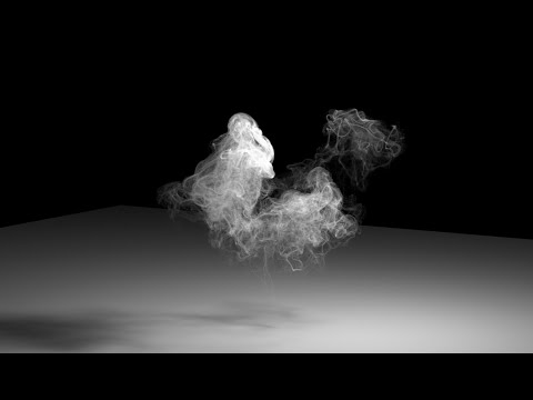
In the following iteration I worked a bit on the Render side.
- added age and life to the points (if you use the POP Network approach age and life are created automatically)
- scattered 1000 points (= 1000 lines)
- created a "density" attribute mapped to the normalized age
- Rasterized a VDB from the curves using Volume Rasterize and sampled the above mentioned density attribute into a Volume Density Attribute
- assigned a simple Pyro shader
- rendered in Mantra
- added a bit of glow and bluish tint in Nuke

Thank you for reading and let me know if you come up with some idea to improve this technique.